-
 Paul Beuchat authoredPaul Beuchat authored
Setup
Contents:
- Vicon
- Firmware and channel
- Network
Vicon
What is Vicon
Vicon is the tracking system for this project. The four cameras in each corner of the room can track the gray markers. One can define objects in the ViconTracker software. Those are then visible in the software or their location data can be shared over a network with others.
Our Vicon Setup
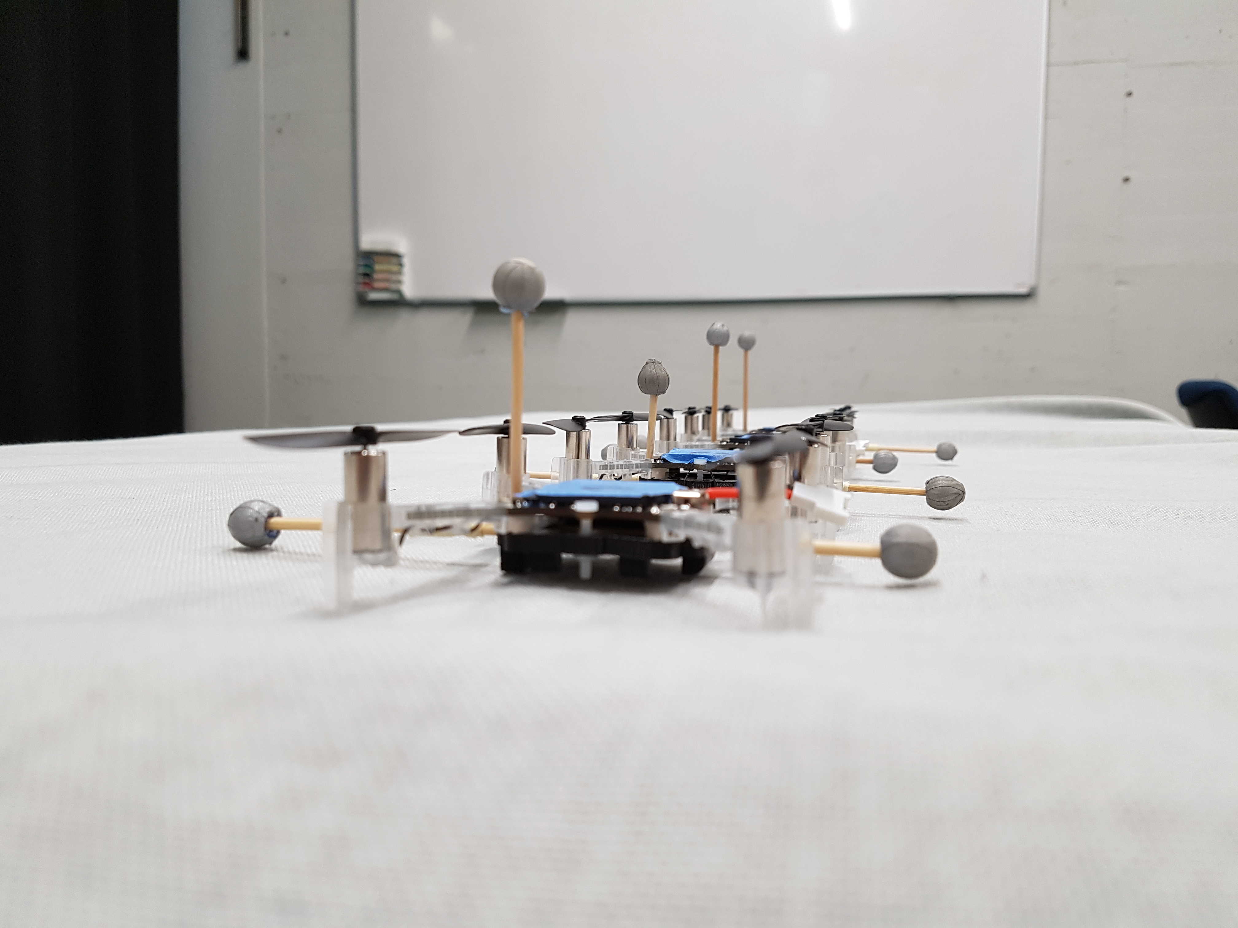 For the PPS we have a separate computer that runs the ViconTracker software. There we define the crazyflie objects that need three markers in slightly different layouts to be distinguishable from another. (see right side)
ViconTracker sends ViconData over the network to the teacher's computer. The teacher computer distributes the data to the students.
Instructions
Calibrating Vicon
-
For calibrating Vicon go to CALIBRATE where you should choose Camera-PixelView as the view type.

-
Click on START in the Calibrate Cameras section. Now you have to walk around the room with the L-wand and swing it in every direction. You can stop when the program is finished.

-
Then you have to lay the wand down somewhere in the room, where you want the origin of the coordinate system to be. How the wand defines the x- and y-axis is shown below. (The handle defines the y-axis, where positive is in direction of orange part. The x-axis is positive in the direction of the longer arm)
Click on SET ORIGIN and you're set.


Defining a CrazyFlie in ViconTracker
-
Go to OBJECTS and choose Camera-3D as the view type
There you should see some markers.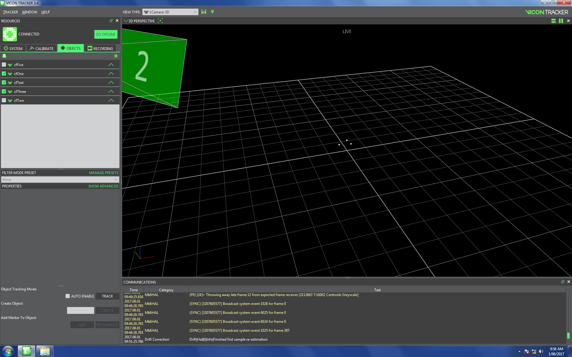
-
Make sure that the crazyflie antenna is facing in the positive x-axis when you define the crazyflie, because the controller relies on this configuration.

-
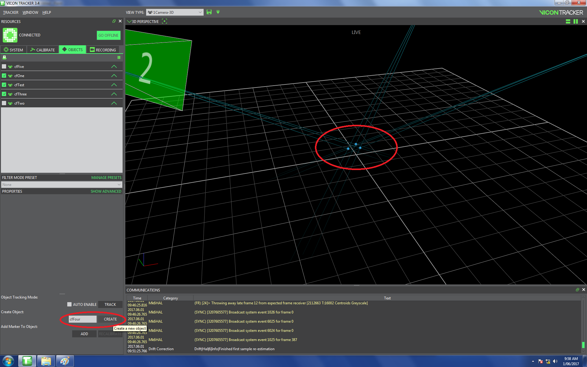
Define an object by
ctrl-rightclickon the markers and name it in the down left corner. Finish by clicking CREATE and saving withctrl-s. Vicon doesn't share the object's data if you don't save.
-
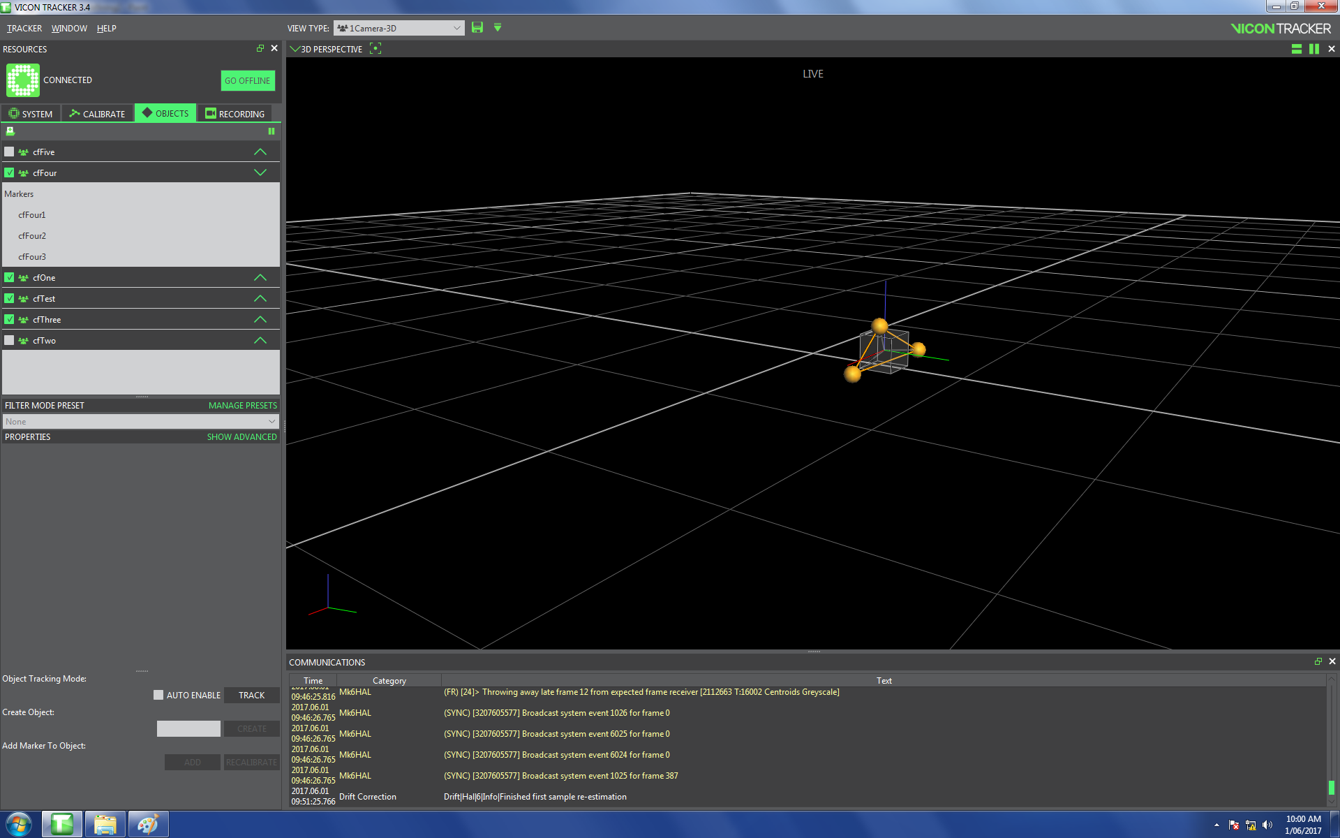
That's how it looks afterwards
Firmware and channel
The firmware of a crazyflie is updated by the teacher. Additionally, the teacher can set the channel of the crazyflies to prevent interference.
Firmware
Instructions for flashing the firmware with the Crazyflie client can be found either here:
https://wiki.bitcraze.io/doc:crazyflie:client:pycfclient:index#firmware_upgrade
or here:
https://www.bitcraze.io/getting-started-with-the-crazyflie-2-0/#update-fw
The compiled versions of the Crazyflie firmware that are compatible with the D-FaLL-System can be found in the crazyflie-firmware folder of the repository.
If you have installed the Crazyflie Client properly, as described in the installation section, it can be started via a terminal window by typing cfclient.
If flashing the firmware on the NRF bluetooth chip, then you must connect the Crazyflie to the computer using a USB cable. If you only need to flash the STM32 main processor chip, this can be done wirelessly and you need to specify the correct address in the Crazyflie Client prior to following the steps below, i.e., the 0xE7E7E7E701 type address.
The steps to flash the crazyflie are:
- Start the Crazyflie Client from terminal using the command
cfclient
- Turn the Crazyflie off
- Start the Crazyflie in bootloader mode by pressing the ON/OFF button for 3 second. Two blue LEDs will start blinking to indicate the the Crazyflie has powered on into bootloader mode
- In the Crazyflie Client, select
Connect -> Bootloaderfrom the top menu. This causes a window titledCrazyflie Serviceto appear
- In the
Crazyflie Servicewindow, press theInitiate bootloader cold bootbutton
- Once the status says
Connected to bootloader, click theBrowsebutton and select the file you wish to flash on the Crazyflie. Typically this file will be something likecf2.binfor flashing only the STM32 main processor, orcrazyflie-firmware.zipfor flashing both the NRF and STM32 processors
- Click the
Programbutton. The progress bar will go from 0% to 100% one time for each of the processors to be flashed
- Wait until the uploading and writing of the new firmware is complete
- Click the
Restart in firmware modebutton. This causes the Crazyflie to reboot and the new firmware is now running
- Turn off the Crazyflie
- Either click the
Cancel bootloadingbutton or simply close theCrazyflie Servicewindow
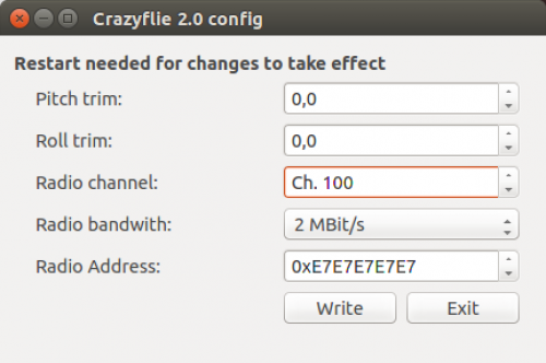
Channel changing
This is also described on the page linked above. Use the following format: 0/xx/2M where xx stands for the radio channel.
The crazyflie has to be restared for the changes to take effect.
Network
Setting up the Vicon network
Inseret the Ethernet cable from Vicon into your computer and go to network settings in the top right corner. Click on Edit Connections...
Choose the Ethernet connection (probably named wired connection 1) and click on edit.

Change the connection name to Vicon.

Then go to the IPv4 Settings and choose Manual as the Method and then add your IP address provided by your teacher (Form 10.42.0.xx). Click tab twice and save.

Don't forget to choose the Vicon network manually if you choose to enable WiFi and Ethernet simultaneously as described below!
Vicon, teacher and students
During installation process is the IP address of the teacher set to 10.42.0.10. (This value is written to the /etc/hosts file such that this IP address is accessible through the keyword teacher)
Have a look at Config.sh in ~/pps_ws/src/d_fall_pps/launch/
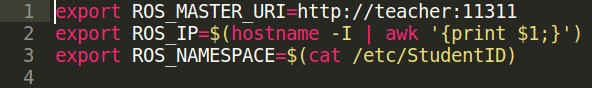
Here you see, that the ROS Master URI is set to be the teacher. This means that roscore runs only on the teacher's computer. Your own IP address (ROS IP) is also set and taken from your Ethernet settings as defined in the section Setting up the Vicon network.
IP-Addresses
Currently the teacher's IP is 10.42.0.10 and the student's IP are of the format 10.42.0.xx, where xx is an unused address.
Using WLAN and Vicon simultaneously
Without some adjustments it is not possible to use an Ethernet and a wireless network at the same time. Vicon is connected via cable and therefore wouldn't allow a connection to the Internet. Because it's tedious to always unplug the cable just to be able to look something up on Google, we provide an explanation on how to enable simultaneous usage of WLAN and Vicon.
But careful: If you enable this setting you have to choose the Vicon network manually. This is a common mistake! You will get an error if the cable is inserted but not manually chosen as shown in the picture below.

Step by Step:
Ubuntu allows multiple connections by default, but sometimes, we need to specify which one to use. Here we use LAN for the Intranet and WiFi for the Internet.
So, firstly search for Network Connections in the unity dash. Then, under the Ethernet section, click 'Add' button.

Then, we need to create a new Ethernet connection which we are going to enable manually. Uncheck the option of connecting automatically since this is your Intranet connection. Choose Vicon as a name instead of Intranet

Then go to the IPv4/IPv6 settings (depending on your network) and then click on the Routes button. Check the 'Use this connection only for resources on its network' option. Click Save.

Now you can use both the LAN and WiFi simultaneously.
Source:
https://askubuntu.com/questions/639100/how-to-get-connection-to-both-wifi-as-well-as-lan-in-ubuntu-14-04-lts#639425
Some additional informations:
http://aleksz-programming.blogspot.ch/2013/01/using-wifi-and-network-cable-at-same.html